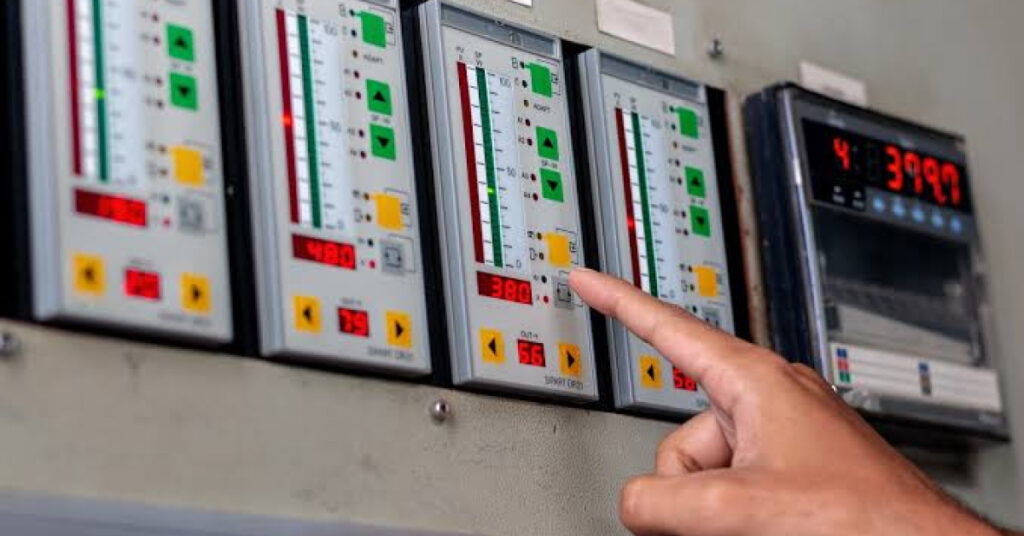
Walk into any chemical refinery, gas processing terminal, or power generation facility in Malaysia, and the physical reality can be overwhelming:
- Thousands of automated valves
- Towering fractionation columns
- Kilometers of interconnected piping
- Dense networks of instrumentation wiring
How do engineers, operators, and maintenance teams maintain absolute control over such massive, complex physical infrastructure?
The answer lies in mastering the Piping and Instrumentation Diagram (P&ID), the universal language and technical DNA of the process industry.
A P&ID is far more than a static engineering drawing; it is a dynamic schematic representation that maps the functional relationship between physical piping, mechanical equipment, instrumentation, and control loops.
Every line designation, valve symbol, and instrument bubble tells a precise story about process flow, pressure ratings, safety interlocks, and operational intent.

[P&ID Blueprint] ──► Defines Line Specs & Instrument Tags ──► Prevents Field Errors
The Cost of Illiteracy: How Misinterpreting P&IDs Triggers Operational Disasters
In professional engineering environments, P&ID literacy is not an optional soft skill, it is a baseline survival requirement. A failure to correctly interpret a drawing during plant modifications, routine maintenance, or emergency response directly precipitates costly equipment damage and hazardous safety incidents:
1. Wrong-Valve Isolation During Turnarounds
When preparing a heat exchanger or hydrocarbon vessel for maintenance, field operators rely on P&IDs to identify isolation block valves and bleeder lines.
Misinterpreting a normally open (NO) versus normally closed (NC) valve symbol, or failing to trace a bypass loop correctly, leads to technicians opening pressurized lines or exposing maintenance crews to toxic chemicals such as hydrogen sulfide ($H_2S$) or benzene.
2. Flawed Management of Change (MOC)
As process plants age, systems are continuously upgraded to optimize yield or resolve bottlenecks.
If junior engineers or contractors fail to read existing P&IDs accurately during the design modification phase, new tie-in connections can overload existing piping schedules, compromise pressure relief valve (PRV) sizing, or induce severe fluid hammer in pump discharge lines.
3. Alarm Floods and Control Loop Confusion
During abnormal plant upsets, control room panel operators must cross-reference Distributed Control System (DCS) alarms against P&IDs in real time.
If an operator cannot quickly decode ISA (International Society of Automation) instrument tagging systems, distinguishing between a Pressure Indicator Controller (PIC), a Level Alarm High-High (LAHH), or a Temperature Differential Transmitter (TDT) response times lag, converting minor operational excursions into emergency facility shutdowns.
Anatomy of a P&ID: Core Competencies for Plant Professionals
To navigate process facilities with confidence, engineering professionals must master four foundational architectural elements of industrial schematics:
| Schematic Element | What It Represents | Critical Engineering Significance |
| Equipment & Vessels | Pumps, compressors, columns, tanks, and reactors. | Defines design capacity, nozzle connections, and elevation requirements. |
| Piping & Line Data | Line sizing, pipe schedules, insulation, and flow direction. | Prevents mismatched metallurgy and ensures velocity limits are respected. |
| Valves & Actuators | Gate, globe, check, and automated control valves. | Dictates fail-safe positions (Fail Open/Fail Closed) during power or air loss. |
| Instrumentation Tags | Sensors, transmitters, logic solvers, and alarms. | Reveals the exact architecture of automated control and safety interlocks. |
Master the Language of Process Systems with Pure Integrity Academy
Whether onboarding fresh engineering graduates, upskilling field technicians, or aligning multidisciplinary project teams, eliminating schematic guesswork is vital for operational excellence.
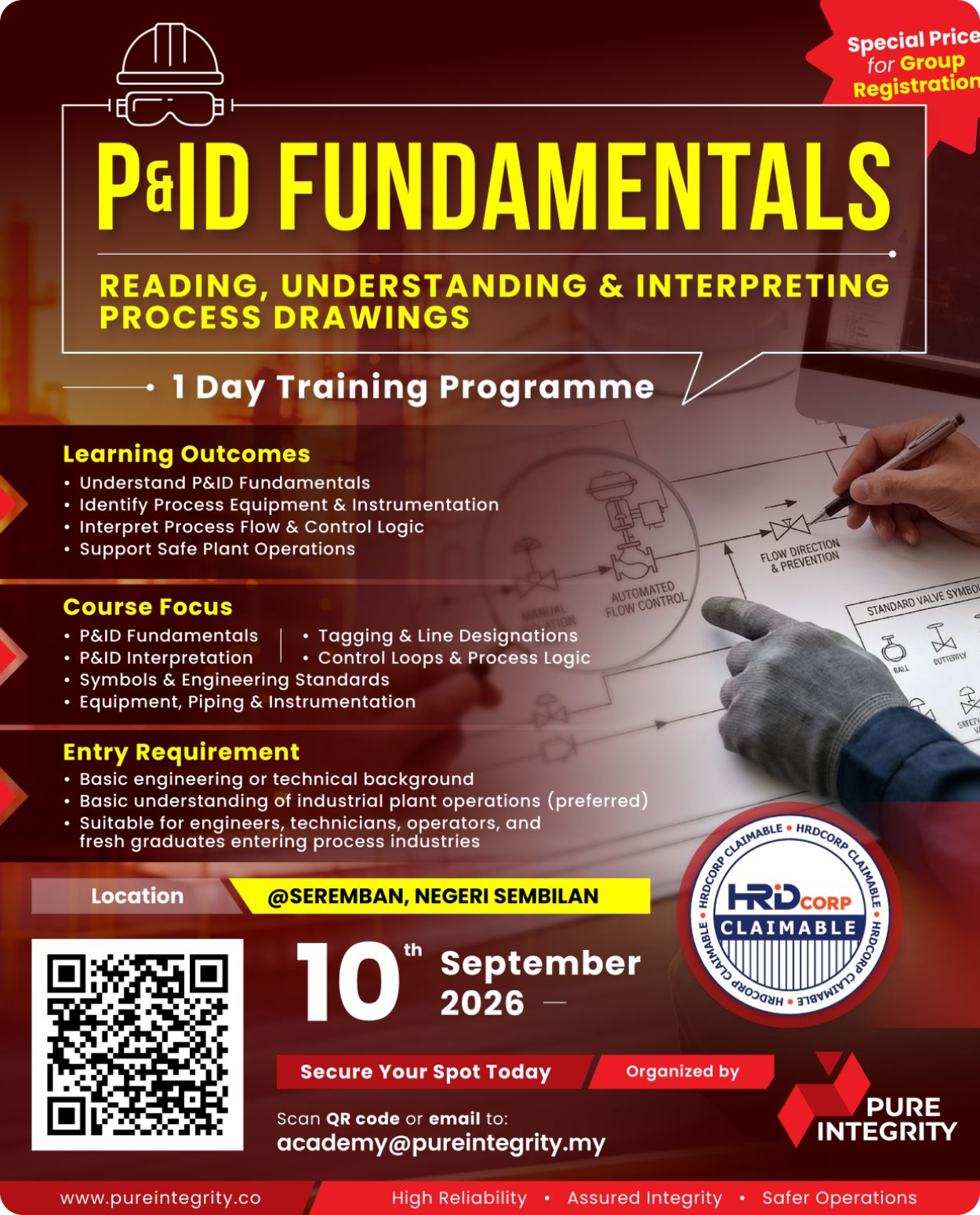
To meet this industry-wide demand, Pure Integrity Academy offers its intensive P&ID Fundamentals Training Programme.
Designed specifically for the Malaysian engineering ecosystem, this course moves away from dry theory, immersing participants in real-world process schematics drawn from actual offshore platforms, refining units, and manufacturing plants.

Key Learning Outcomes:
-
Fluency in Standardized Symbology: Read and interpret complex ISA and international P&ID symbols with zero hesitation, recognizing piping configurations, instrumentation loops, and mechanical equipment instantly.
-
Decoding Tagging & Nomenclature: Master numbering conventions, line designations, metallurgy codes, and equipment identification strings used across major engineering EPCs and operating companies.
-
Process Flow & Control Strategy Comprehension: Trace fluid flow from feed inlet to product export, understanding how feedback loops, cascade control, and safety shutdown interlocks protect the facility in real time.
-
Enhanced Field Safety & Troubleshooting: Empower operators and maintenance supervisors to execute error-free line tracing, isolation tagging, and rapid root-cause troubleshooting during plant disturbances.
Upcoming Session Details:
- Date: 10 September 2026
- Location: Seremban, Negeri Sembilan
- Target Audience: Engineers, Technicians, Plant Operators, Supervisors, and Fresh Graduates
- Funding: 100% HRD Corp Claimable
- Notes : Highly Attractive Corporate Group Rates Available
Review : HRD Corp Claimable Courses
Equip your technical workforce with the industry’s most essential skill. Secure your seats now by contacting our training desk: academy@pureintegrity.my
Published in July 2026
Source : LinkedIn